

Table of Contents
Your Composites Engineering Partner
Element 6 Composites specializes in carbon fiber design, analysis, prototyping, and manufacturing. We partner with engineering teams to turn performance requirements into practical, manufacturable composite solutions.
Our team brings deep experience in carbon fiber composites and other high-performance materials. This guide will help you understand the key considerations for carbon fiber design and application, from early material selection through production.
What is Carbon Fiber?
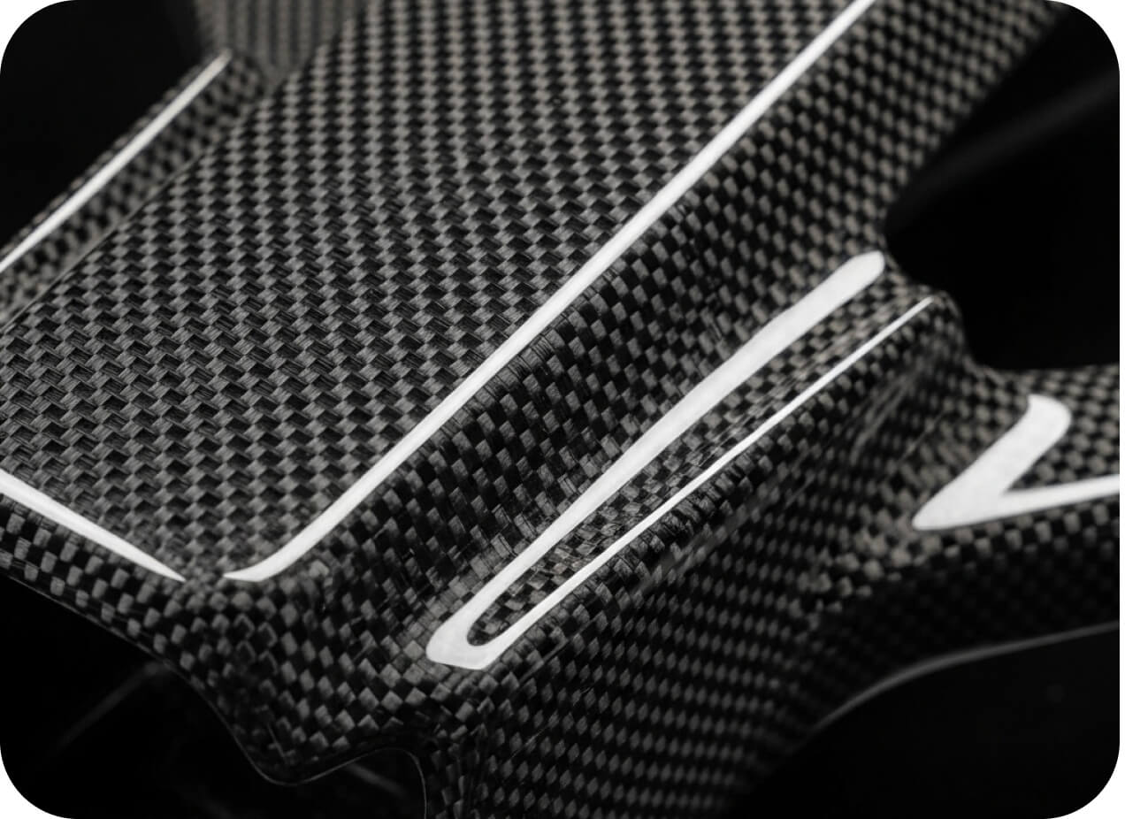
Carbon fiber is composed of strands of fibers 5 to 10 microns in diameter that consist of long, tightly interlocked chains of carbon atoms in a microscopic crystalline structure.
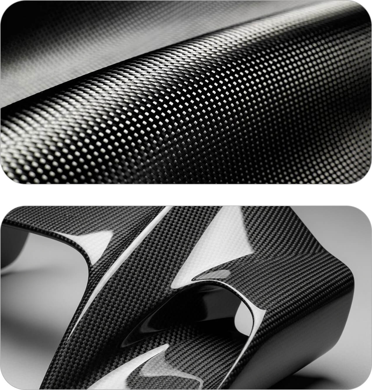
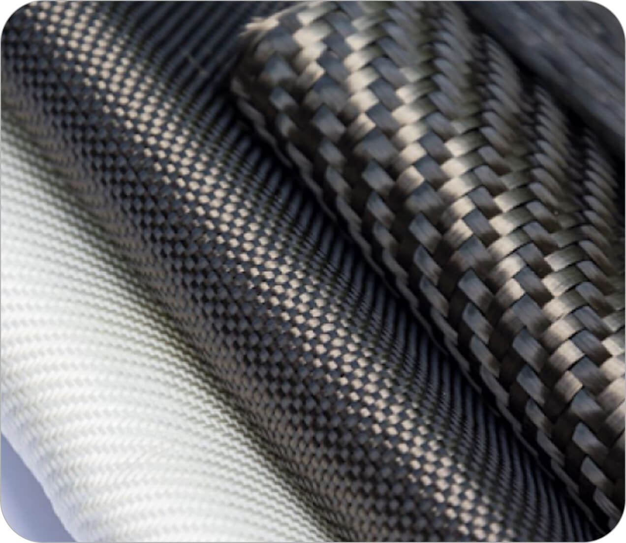
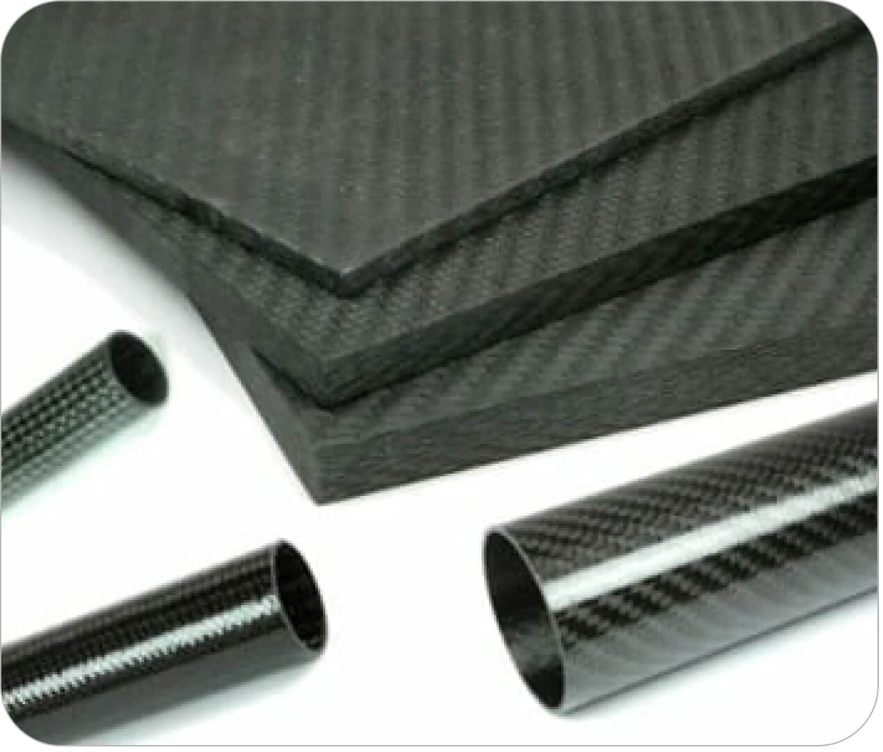
These fibers are extremely stiff, strong, and light, and are used in many processes to create high-performance building materials. Carbon fiber reinforcements come in a variety of weaves, braids, and other formats, such as tow and unidirectional.
These are combined with various resins to produce carbon fiber-reinforced composites in a wide range of shapes and fiber patterns.
How is Carbon Fiber Made?

Precursor
To produce carbon fiber, an organic polymer precursor is needed. This raw material is processed with heat and chemical agents to convert it to carbon fiber. The first high-performance carbon fiber materials were made from a rayon precursor. Currently, approx 90% of carbon fiber is made from polyacrylonitrile, while the other 10% or so is made from rayon or petroleum pitch.

Manufacturing
For the most common polyacrylonitrile (PAN)-based process, carbon fiber manufacturing begins by spinning the precursor polymer into continuous fibers. These fibers undergo stabilization in air, where controlled heating and oxidation prepare their molecular structure for higher temperatures. The stabilized fibers are then carbonized in an oxygen-free, inert atmosphere, preventing combustion as heat removes most non-carbon elements. Carefully controlled temperatures and fiber tension help develop the carbon structure that gives the fibers their high strength and stiffness.

Treatment
Following carbonization, the surface of the carbon fibers must be treated to improve bondability with epoxies or other resins. Careful oxidation of the carbon fiber surface improves chemical bonding, while simultaneous surface roughening enhances mechanical bonding. This oxidation can be accomplished in several ways. The carbon fiber can be exposed to various gases, such as carbon dioxide or ozone, or liquids, such as nitric acid, or even processed electrolytically.

Sizing
Prior to weaving, the carbon fibers must be sized, or coated, with a polymer to protect them during weaving. The sizing is selected for compatibility with the laminating resin to be used. The fibers are then wound onto bobbins and processed into various weaves and other formats.
The Ultimate Guide to Carbon Fiber Design and Application
Why Use Carbon Fiber?
Reason 1 — High Stiffness at Low Weight
The primary reason to consider carbon fiber is its high stiffness-to-weight ratio. Carbon fiber is very strong, very stiff, and relatively light.
The stiffness of a material is measured by its modulus of elasticity. For example, Grafil 34-700 carbon fiber has a tensile modulus of approximately 34 MSI (234 GPa) and an ultimate tensile strength of approximately 700 KSI (4.8 GPa). These values describe the individual reinforcing fibers along their length, rather than a finished carbon fiber composite part.
For comparison, aluminum has a modulus of approximately 10 MSI, while steel is approximately 30 MSI. A finished composite’s properties depend on the fiber grade, resin system, fiber content, and laminate orientation. The illustrative laminate values in the comparison table below show how these factors affect the stiffness-to-weight and strength-to-weight advantages of a carbon fiber structure.
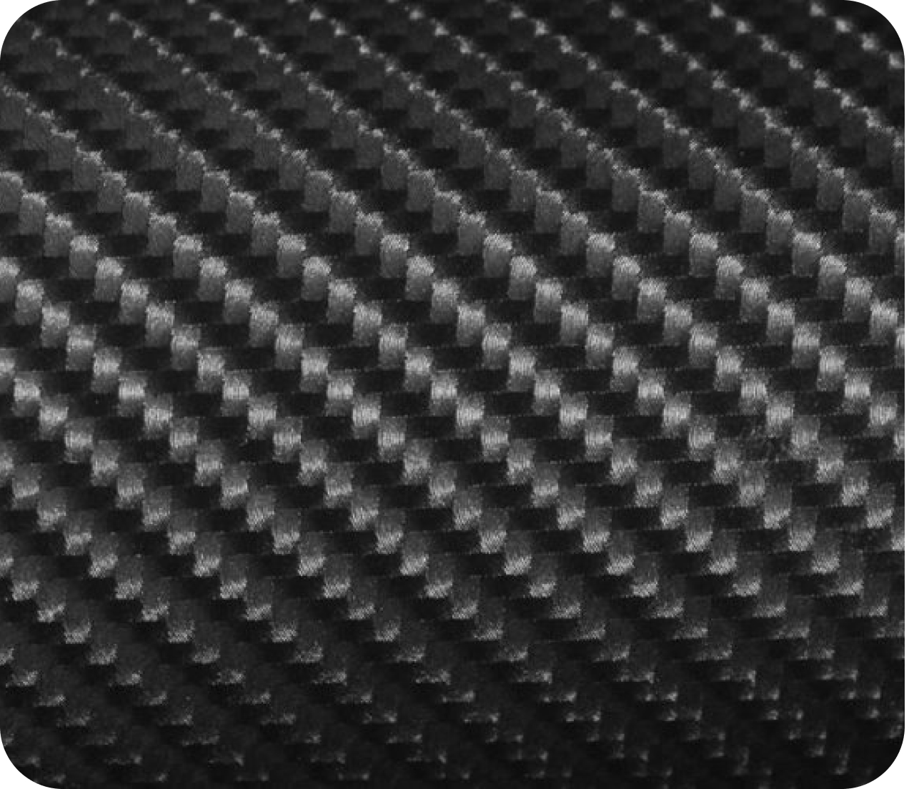
Ultra-High Modulus Carbon Fiber
High and Ultra-High Modulus carbon fiber, or High Strength carbon fiber, are also available due to refinements in the materials and the processing of carbon fiber.
A composite carbon fiber part is a combination of carbon fiber and a resin, typically epoxy. The strength and stiffness of a carbon fiber composite part will be the result of the combined strengths and stiffnesses of both the fiber and the resin.
The magnitude and direction of local strength and stiffness of a composite part are controlled by the local fiber density and orientation in the laminate.
Balanced & Symmetric Laminates
Specific stiffness and specific strength describe a material’s elastic modulus and strength relative to its density. These measures help engineers compare materials when reducing weight can improve performance or reduce life-cycle cost.
For this comparison, consider a standard-modulus, plain-weave carbon fiber plate with a balanced, symmetric 0/90 layup, an approximate elastic bending modulus of 10 MSI, and a density of 0.050 lb/in³. Dividing the modulus by the density gives a specific stiffness of 200 MSI·in³/lb.
Using a strength value of 90 KSI for this illustrative laminate comparison gives a specific strength of 1,800 KSI·in³/lb. Actual laminate properties depend on the fiber, resin, manufacturing process, loading direction, and test method. Material selection and structural design require data representative of the intended construction.
| Material | Specific Stiffness MSI·in³/lb | Specific Strength KSI·in³/lb |
|---|---|---|
| Carbon fiber laminate Balanced, symmetric 0/90 example | 200 | 1,800 |
| 6061-T451 Aluminum | 100 | 350 |
| 4130 Steel Hardened and tempered, 125 KSI level | 100 | 417 |
Illustrative comparison using rounded inputs. The composite example uses bending modulus and a 90 KSI strength input; the metal examples use elastic modulus and ultimate tensile strength. Values are not design allowables or a direct equivalence between parts.
Compared with Aluminum or Steel
For comparison, Kaiser Aluminum publishes an elastic modulus of 10 MSI and a typical ultimate tensile strength of 35 KSI for 6061-T451 aluminum. Using a rounded density of 0.10 lb/in³ gives a specific stiffness of 100 MSI·in³/lb and a specific tensile strength of 350 KSI·in³/lb.
For a hardened-and-tempered 4130 steel example at the 125 KSI tensile-strength level specified by SAE AMS6346D, using an approximate elastic modulus of 30 MSI and a rounded density of 0.30 lb/in³ gives a specific stiffness of 100 MSI·in³/lb and a specific tensile strength of approximately 417 KSI·in³/lb.
With these inputs, the illustrative carbon fiber laminate has approximately twice the specific stiffness, five times the specific strength of the aluminum example, and four times that of the steel example. These ratios illustrate the potential weight advantage of composites; they do not establish equivalent part performance or a direct replacement thickness. Laminate construction, loading, geometry, buckling, and connections must also be evaluated.
Sandwich Structures
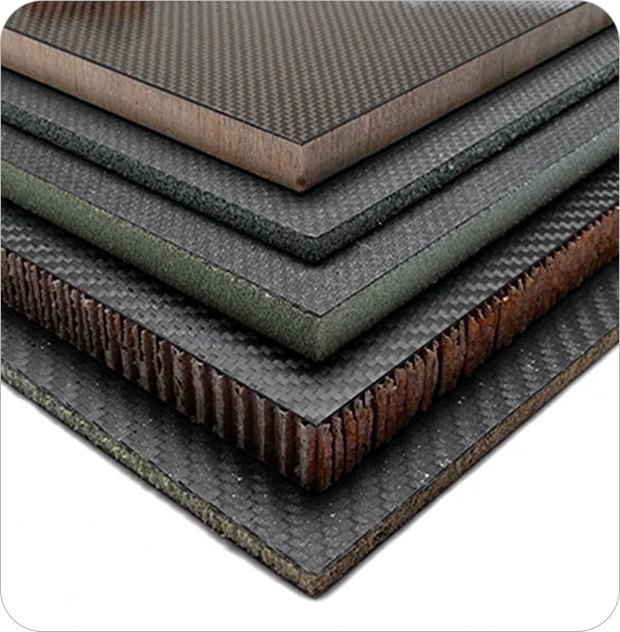
When one considers the option of customizing carbon fiber panel stiffness through strategic fiber placement and includes the significant increase in stiffness possible with sandwich structures utilizing lightweight core materials, it is clear how carbon fiber composites can benefit a wide variety of applications.
The specific numbers depend on the construction details and the application. For instance, a foam-core sandwich has an extremely high strength-to-weight ratio in bending, but not necessarily in compression or crush. In addition, the loading and boundary conditions for any components are unique to the specific structure.
Thus, it is impossible to provide the thickness of a carbon fiber plate that would directly replace a steel plate in a given application without careful consideration of all design factors. This is accomplished through careful engineering analysis and experimental validation.
Reason 2 — Dimensional Stability
Dimensional stability is an important benefit of carbon fiber composites, especially in applications where temperature changes could affect alignment, fit, or precision. Carbon fibers typically have very low—and sometimes negative—thermal expansion along their length. For comparison, steel has a coefficient of thermal expansion of approximately 7 × 10⁻⁶ in/in/°F, while aluminum is approximately 13 × 10⁻⁶ in/in/°F, depending on the alloy and temperature range.
The thermal expansion of a finished carbon fiber component depends on the fiber type, resin system, fiber volume, and laminate orientation. By selecting an appropriate layup, engineers can design structures with low thermal expansion in the directions most important to the application. This can help maintain the position of sensors, cameras, optical components, and other precision equipment as operating temperatures change.
Dimensional stability also requires attention to connections. When carbon fiber is joined to metals, differences in thermal expansion can create stresses or shift alignment. Element 6 Composites considers the laminate, operating environment, and attachment details together to develop structures that maintain the required dimensional performance.
Reason 3 — Tailorable Material Properties
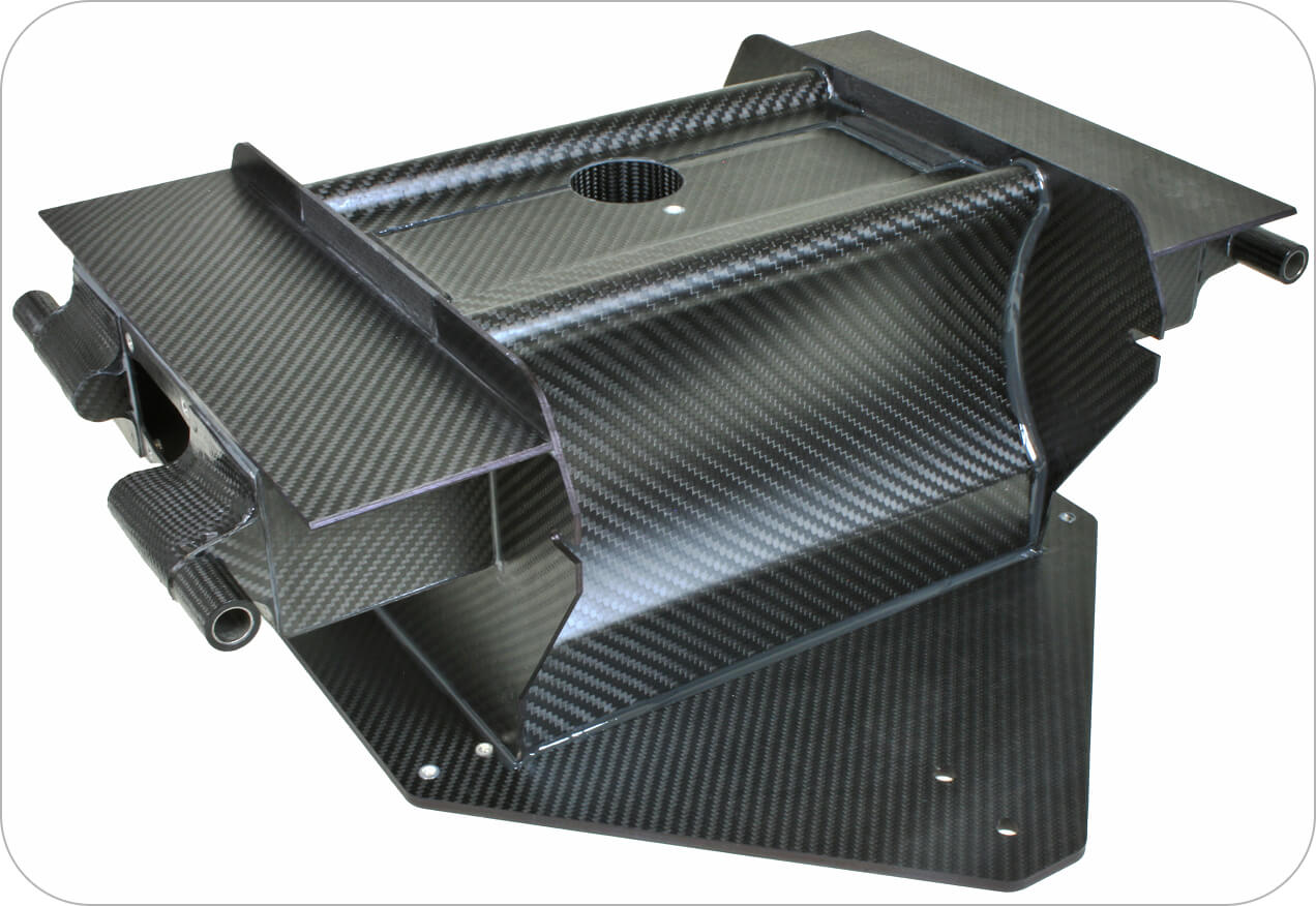
When designing composite parts, engineers must consider how material properties vary with direction. Common metals such as steel and aluminum are generally modeled as homogeneous and isotropic, with similar properties in all directions. However, carbon fiber composite properties depend strongly on fiber orientation, fiber content, and laminate construction.
Engineers can arrange carbon fiber reinforcement to maximize strength and stiffness along a particular axis or use a quasi-isotropic layup to achieve approximately uniform properties within the plane of the laminate. This flexibility allows the material to be tailored to the part’s loads and performance requirements.
Designing for Directional Stiffness
One example of design flexibility in carbon fiber is the custom design of beams with tailored stiffness along specific axes.
Element 6 Composites has developed patent-pending methods for fabricating carbon-fiber tubes to achieve optimal stiffness along each bending axis. Such tubes are similar to I-Beams in their bending resistance, yet retain the high torsional stiffness of a tube.

Carbon Fiber Engineering
Occasionally, potential customers call us and ask, “Can you copy this steel part in carbon fiber?” The answer is typically, “That is probably not a good idea.” In most cases, it doesn’t make sense to design a part for metal and then just replace the metal with carbon.
Carbon fiber delivers its greatest benefit when the component is designed around the material rather than treated as a direct substitute for metal. Our engineers work with customers to understand loading, stiffness, weight, geometry, manufacturing volume, and cost before developing the laminate and manufacturing approach.

Carbon Fiber Design
The carbon fiber design process begins with a clear understanding of the application’s requirements. Applied loads, allowable deflection, available space, operating environment, and attachment points establish the performance goals. Production quantity, target cost, dimensional tolerances, and appearance also influence the design. Defining these inputs early helps our engineers develop a practical solution that meets both technical and manufacturing requirements.
Element 6 Composites develops the part design and manufacturing approach together. Through iterative cycles of CAD modeling, engineering analysis, and cost evaluation, we refine the geometry, fiber orientations, laminate thickness, and connection details. Designing around the capabilities of carbon fiber composites allows us to place reinforcement where it is most effective, rather than simply reproducing a part originally designed for metal.
Learn more about our carbon fiber design services for custom components and assemblies.
Team of Carbon Fiber Engineers
Our team of engineers, designers, and technicians have decades of experience in product development, research, and invention.
Combining creativity with precision engineering, Element 6 Composites takes pride in helping customers develop practical and elegant solutions, whether for a single prototype or for a production run of thousands of parts.


Carbon Fiber Analysis
Our current computational tools include NeiNastran for Finite Element Stress analysis of composites. Our FEA experience ranges from advanced carbon fiber truss structures to prosthetics to wind turbines and unmanned aerial vehicles in a wide variety of applications.
In addition to our internal expertise, we have relationships with experts available to support us with unusual or particularly challenging analyses. One example involved an NYSTAR grant we received, which allowed us the opportunity to work with Cornell University to test our carbon fiber materials. This provided excellent data for model refinements and internal design databases.
Carbon Fiber Prototyping
Carbon fiber prototyping connects engineering analysis with real-world performance. A prototype may be a material test specimen, a critical joint, an individual component, or a complete assembly. The appropriate scope depends on what needs to be validated, including fit, stiffness, load capacity, connection performance, or manufacturing feasibility.
Our engineers and experienced craftsmen work together to produce prototypes that answer these questions before committing to production. Testing helps identify where the geometry, laminate, tooling, or assembly method needs refinement. Where practical, prototypes use the intended production materials and processes so the results inform the final manufacturing approach. Prototypes can also support customer demonstrations and marketing, with attention to both function and appearance.
Explore our carbon fiber prototyping services to see how we help validate designs before production.


Carbon Fiber Manufacturing
Carbon fiber manufacturing turns an engineered design into a repeatable composite part. Selecting the right process depends on part geometry, production quantity, laminate requirements, dimensional tolerances, surface finish, and tooling cost. Manufacturing individual carbon fibers is a separate upstream process; our work focuses on combining fiber reinforcement and resin to produce finished components and assemblies.
Element 6 Composites uses processes including wet layup, vacuum bagging, matched tooling, vacuum-assisted resin transfer molding (VARTM), and pultrusion, along with proprietary fabrication methods. Our engineers and manufacturing team evaluate the approach during design and prototyping, accounting for material placement, consolidation, curing, trimming, machining, and assembly. Inspection and testing appropriate to the project help verify that finished parts meet the agreed requirements, from a single custom component to a production run.
Learn more about our carbon fiber manufacturing services for custom parts and production programs.
Carbon Fiber CNC Machining
With more than 35 years in business, Element 6 Composites is a leading New York manufacturer of carbon fiber products for a wide variety of applications. Our capabilities include CNC machining of carbon fiber, aramid, and other fiber-reinforced composites. The conductivity, stiffness, and brittle behavior of carbon fiber composites require specialized tools and machining techniques.
Composites enable optimization of parts for strength, stiffness, and design simplicity. From simple components to complex assemblies, we combine advanced fabrication techniques with our three core strengths—Innovation, Technology, and Creativity—to deliver practical, high-performance solutions.

Carbon Fiber Structures

Carbon Fiber Structural Design
Carbon fiber structural design begins with understanding how a structure will carry loads and how much it can safely deflect. Applied forces, support conditions, attachment points, and operating environments all influence the design. Unlike metals, carbon fiber composites allow engineers to tailor stiffness and strength through fiber orientation, laminate thickness, and member geometry. An effective design places reinforcement where it contributes most to performance while accounting for weight, manufacturability, and cost.
Connections are equally important to the performance of a carbon fiber structure. Bonded joints, gussets, and mechanical connectors must transfer loads between members without creating excessive local stresses. Element 6 Composites develops the members and connections together, using engineering analysis to evaluate the proposed structure and prototype testing to validate critical assumptions. This approach supports lightweight beams, trusses, and frames designed around the requirements of each application.
Trusses and Beams
Carbon fiber composites offer an alternative to conventional materials, such as steel or aluminum, for constructing lightweight trusses and frame structures.
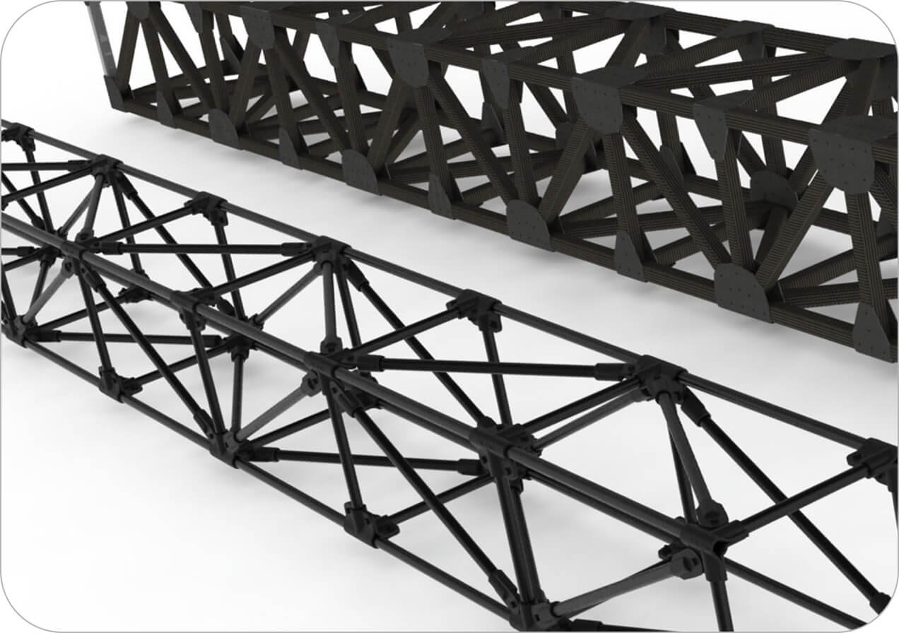
Element 6 Composites has developed three systems for designing and fabricating carbon fiber tubular structures: two optimized for high strength, robustness, and customization, and one for reduced weight and lower cost.


Square Tubes and Gussets
The first high-strength, robust construction system uses rectangular and square tubes, with gussets connecting them. The tubes range in size from 3/4” x 3/4” to 2” x 4” and larger. In addition to overall dimensions, wall thicknesses, gusset geometries, and layup schedules can be customized to meet the needs of each application.
For example, unidirectional carbon fiber can be added to individual members to increase bending/axial stiffness and strength. Likewise, gusset thickness and geometry can be adjusted to ensure proper load transfer through the joints. NeiNastran composite FEA calculations can be used to optimize structures for minimum weight while maintaining the specified strength and stiffness requirements.
Modular Connectors and Roll-Wrapped Tubes
DragonPlate now offers a full line of patented Modular Carbon Fiber Tube Connectors that make it very easy to build strong, robust structures with roll-wrapped carbon fiber tubes.
The Modular connectors are typically bonded at the ends of the tubes and connected to one another with bolts. Multiple tubes can be connected with a single bolt that can be easily removed for quick disassembly and later reinstalled.
Simple pinned joints allow infinite choices in attachment angles. Tubes can be attached to plates or other mounting brackets. Modular connectors with end threads allow easy attachment of hardware, sensors, cameras, and other components. The connector is easily bonded into the tube with a patented joint design that is exceptionally strong.


Pultruded Tubes and Connectors
An alternative, lightweight, and cost-effective carbon fiber construction method uses our patented connectors and pultruded carbon fiber tubes. This system provides a great deal of versatility to the structural designer, with infinite combinations of lengths and angles, and a wide array of attachment components.
In addition, the skills required to construct this type of structure are very easy to master. Element 6 Composites specializes in both design and fabrication; however, many of our customers have the in-house capability to assemble the final carbon fiber truss structures once we have worked together through the design and prototyping phases.
Carbon Fiber Structural Beams
Many applications, from robots to load-bearing structures, require customized carbon fiber structural beams. Element 6 Composites specializes in designing and fabricating custom carbon fiber structural beams for a wide array of industries and users.
Although these beams are typically more expensive than similar metal components, the substantial weight savings achievable with advanced composites often outweigh the upfront investment.

The Ultimate Guide to Carbon Fiber Design and Application

Carbon Fiber Applications
Carbon fiber composites support a wide range of applications, from tactical bridges and ladders to musical instruments, unmanned vehicles, and industrial robotics. Each application draws on a different combination of benefits, including low weight, high stiffness, strength, dimensional stability, and tailored material properties.
Element 6 Composites works with customers to match the material, structural design, and manufacturing approach to their performance requirements. The examples below illustrate how carbon fiber can solve practical engineering challenges across industries.
Carbon Fiber Tactical Bridges and Ladders
Carbon fiber composites provide substantial advantages over conventional materials in the construction of advanced tactical carbon fiber ladders and bridges.
Element 6 Composites has worked with both the military and law enforcement to develop a wide range of patented lightweight tactical carbon fiber ladders, platforms, and bridges, ranging from extremely lightweight ladders to heavy-duty segmented ladders and bridges.


Carbon Fiber in Musical Instruments
In addition to industrial and military applications, the team at Element 6 Composites has a strong interest in applying carbon fiber composites to music and acoustic resonance.
Element 6 has been privileged to work with some of the preeminent instrument builders and researchers, resulting in the development of numerous unique applications for carbon-fiber stringed-instrument building.
Unmanned Vehicles
Element 6 Composites has worked with multiple companies to help develop and manufacture a variety of unmanned ground and air vehicles. Combining decades of experience in composites, structural design, and aerodynamics, Element 6 Composites supports customers in basic configuration design and analysis, component optimization, prototyping, and production manufacturing.
With a history of projects ranging from military ground robotics to lighter-than-air vehicles to rigid-wing and vertical takeoff and landing carbon-fiber UAVs, we have both the expertise and the facilities to support your project.


Automation and Robotics
Facilities that incorporate industrial automation into their manufacturing processes continually strive to improve efficiency by increasing speed and precision.
Often, the most direct means of achieving these goals is reduced weight and increased stiffness of the robotics, particularly the robotic end effectors. Lightweight end effectors translate directly to increased speed on the production line, higher precision, reduced motor and actuator loads, and improved reliability.
Ready to Start Your Project?


© 2026 Element 6 Composites. All Rights Reserved