What is Carbon Fiber?
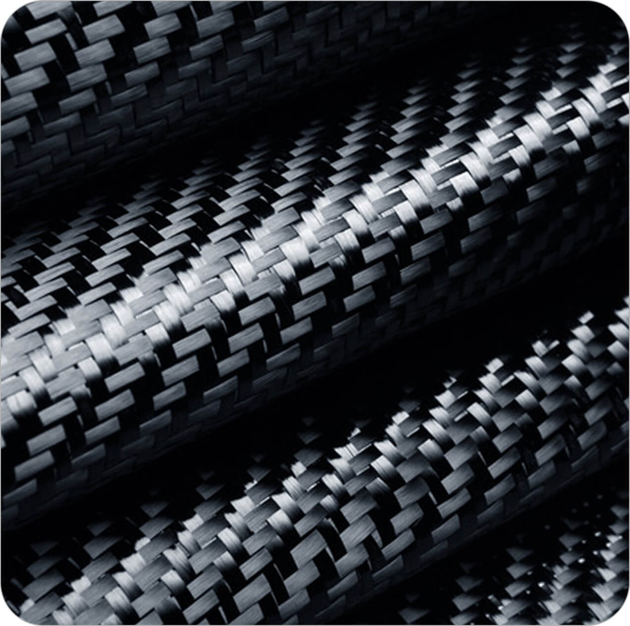
Carbon fiber is made from tightly bonded carbon atoms arranged in long, chain-like structures. These fibers are exceptionally strong, lightweight, and rigid — characteristics that make them ideal for high-performance applications across industries ranging from aerospace to sporting goods.
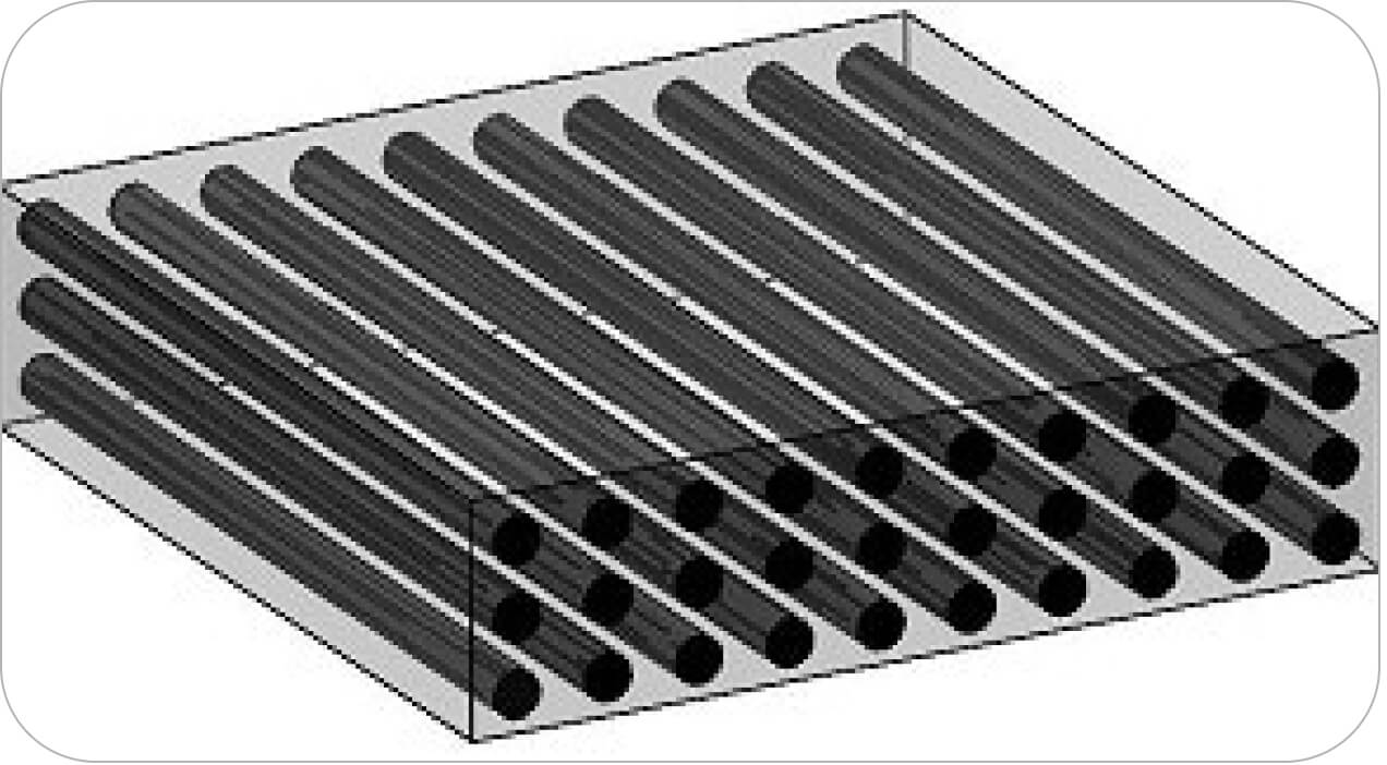
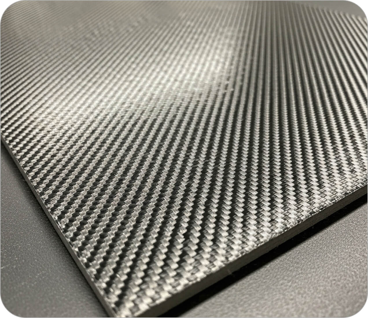
As a raw material, carbon fiber is available in several forms, including yarns, unidirectional tapes, woven fabrics, and braided structures. Each format offers unique advantages during the composite manufacturing process and serves as a foundational building block for producing advanced, high-strength components.

Tension & Compression
Carbon fiber composites derive their exceptional strength from the ability of the fibers to perform under both tension and compression. Within these two mechanical modes, performance can be further refined through careful selection of material parameters — most notably the type of carbon fiber weave. Different weave patterns influence both the fabrication process and the final structural behavior of the part, including stiffness, flexibility, and load distribution.
To form a reliable composite component, carbon fibers must be embedded in a stable matrix, typically a polymer resin. This matrix secures the fibers, preserves their alignment, and ensures the part maintains its shape and strength under stress.
Epoxy Resin is An Excellent Plastic
Epoxy resin is a high-performance thermoset polymer widely used as the matrix in carbon fiber composites. It provides good compressive and shear properties compared to other resins, and plays a vital role in binding the fibers, preserving their alignment, and transferring loads throughout the structure. While epoxy is significantly less strong and stiff than the carbon fibers themselves, it is essential for maintaining the structural cohesion of the part — holding fibers in place, enabling load transfer between them, and helping the composite function effectively under complex stress conditions.
Composite fabrication can be achieved through various techniques, each suited to different production goals. Common methods include wet lay-up, vacuum bagging, resin transfer molding (RTM), matched-die tooling, insert molding, pultrusion, and more. Each approach influences the final part’s strength, weight, and surface finish.
Epoxy formulations can be tailored to meet specific performance requirements — such as faster or slower cure times, UV resistance, high-temperature stability, flame retardancy, or enhanced fracture toughness through specialized additives and modifiers.

Strength, Stiffness, and Comparisons With Other Materials
Carbon fiber is extremely strong. It is typical in engineering to measure the benefit of a material in terms of strength to weight ratio and stiffness to weight ratio, particularly in structural design, where added weight may translate into increased life cycle costs or unsatisfactory performance.
The stiffness of a material is measured by its modulus of elasticity. The modulus of carbon fiber is typically 20 msi (138 Gpa) and its ultimate tensile strength is typically 500 ksi (3.5 Gpa).
High stiffness and strength carbon fiber materials are also available through specialized heat treatment processes with much higher values. Compare this with 2024-T3 Aluminum, which has a modulus of only 10 msi and ultimate tensile strength of 65 ksi, and 4130 Steel, which has a modulus of 30 msi and ultimate tensile strength of 125 ksi.
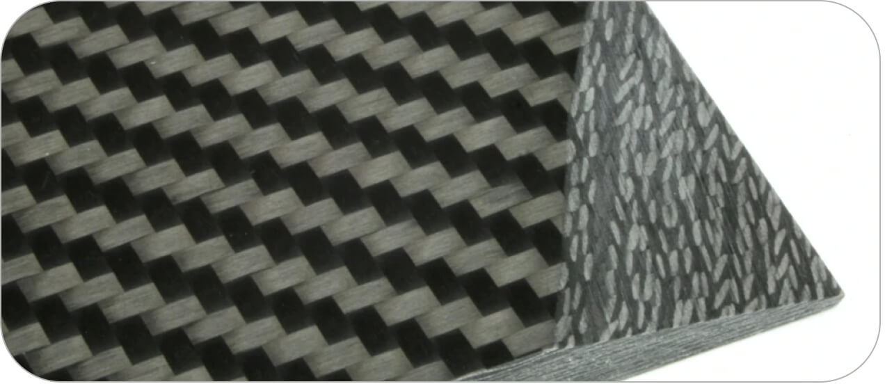
Carbon Fiber Reinforced Laminate
Consider a basic plain-weave carbon fiber reinforced laminate: it typically exhibits an elastic modulus of approximately 6 million psi (41 GPa) and a volumetric density of about 83 lb/ft³. This results in a stiffness-to-weight ratio of roughly 1.07 × 10⁷ ft, a key performance metric in structural design where mass efficiency is paramount.
For comparison: Aluminum (2024-T3) has a density of 169 lb/ft³, yielding a stiffness-to-weight ratio of approximately 8.5 × 10⁶ ft. 4130 Steel has a much higher density of 489 lb/ft³, but a slightly better stiffness-to-weight ratio at 8.8 × 10⁶ ft.
Even in this basic laminate form, carbon fiber offers a stiffness-to-weight ratio that is 18% higher than aluminum and 14% higher than steel. And this is just the starting point.
Through strategic laminate design, stiffness and strength can be tailored directionally, allowing engineers to reinforce specific load paths and optimize structural behavior. Furthermore, when carbon fiber laminates are combined with lightweight core materials in a sandwich structure, both bending stiffness and panel strength can increase dramatically without adding significant weight.
One practical example of this is in the design of beams or panels with tailored stiffness along orthogonal axes, enabling application-specific performance in aerospace, automotive, marine, and architectural components.
Patent Pending Methods
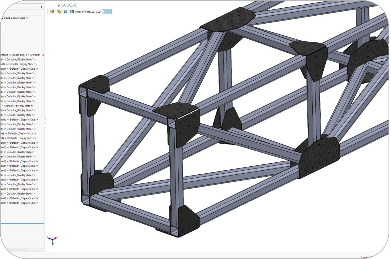
Element 6 Composites has developed patent-pending methods for the fabrication of carbon-fiber tubes for optimum stiffness along each bending axis, with the order of magnitude differences in rigidity. Such tubes are similar to I-Beams in their resistance to bending, yet retain the high torsional stiffness found in a tube, as well as ease of assembly.
Design Limitations & Considerations
Carbon fiber reinforced composites offer a unique combination of mechanical and aesthetic advantages that can be strategically leveraged in the design of advanced systems. Most notably, they excel in applications requiring a high strength-to-weight or high stiffness-to-weight ratio — making them indispensable in performance-critical environments.
Key industries that benefit from carbon fiber include:
- Aerospace and military structures, where weight savings translate directly to fuel efficiency and mission success
- Robotics and automation, where stiffness enables precision and dynamic responsiveness
- Medical devices and imaging systems, where lightweight materials reduce mechanical load and enhance user control in high-precision tools
- High-performance sporting goods, such as bicycles, racquets, and skis, where energy transfer and lightweight design enhance user experience
- Manufacturing jigs and fixtures, where rigidity and low mass reduce inertia and improve throughput
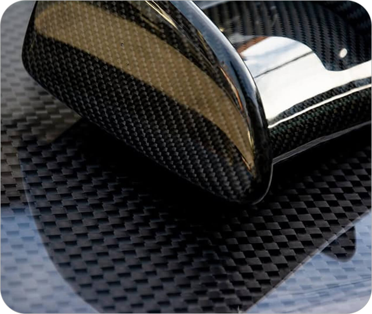
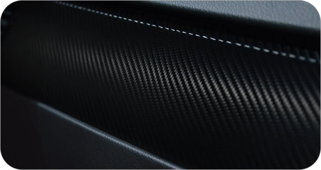
Beyond performance, carbon fiber also delivers a refined, high-tech aesthetic. The visual appeal of exposed weave patterns—often finished with a clear, high-gloss coating—has made carbon fiber synonymous with modern engineering precision and elevated product design, across both industrial and consumer-facing applications.

Localized Stress Concentrations
While carbon fiber composites offer many performance advantages, engineers must also carefully evaluate their tradeoffs. One key characteristic is that carbon fiber does not undergo plastic deformation. Unlike metals, which can yield and permanently deform under excessive load, carbon fiber maintains its shape elastically—until its ultimate strength is exceeded, at which point it can fail suddenly and catastrophically. This makes the consideration of safety factors and failure modes critical in structural design.
A common design challenge arises in areas of localized stress concentrations, such as holes, sharp internal corners, or notches. In metals, stress tends to redistribute through local yielding around these features. In contrast, carbon fiber typically fails by forming a localized crack, especially if the fiber orientation around the feature is not properly managed. Even when a carbon fiber part exhibits superior stiffness and strength compared to a metal counterpart, improper attention to load paths and fiber direction near stress risers can lead to premature failure.
High Optimized Parts
Additionally, carbon fiber composites come with higher material and manufacturing costs than traditional materials. Producing high-quality components — such as solid laminates, sandwich panels, or custom-formed structures — requires a skilled workforce, specialized equipment, and tightly controlled fabrication processes. Precision in layup, curing, tooling, and quality assurance is essential to realize the full potential of the composite.
Anisotropy in Composite Design
When designing with composite materials, it's not appropriate to make direct, one-to-one property comparisons between carbon fiber and traditional engineering materials like steel, aluminum, or plastics. These conventional materials are typically homogeneous — meaning their properties are uniform throughout the volume — and isotropic, which means their mechanical behavior is the same in all directions.
Carbon fiber composites, on the other hand, behave very differently. The strength and stiffness of a carbon fiber part are directional, concentrated along the axis of the fibers. As a result, the overall performance of the part depends heavily on how the fibers are oriented, stacked, and distributed during the layup process. This makes carbon fiber inherently anisotropic and non-homogeneous.
Designing effective composite structures requires an understanding of these material characteristics. Engineers must tailor fiber architecture to align with expected loads, ensuring that the fibers carry stress efficiently while minimizing weak points across unsupported axes.
Strength-to-Weight Ratio and Structural Design
Carbon fiber composites are widely known for their exceptionally high strength-to-weight and stiffness-to-weight ratios—far exceeding those of traditional materials like steel or unreinforced plastics. However, the actual performance of a carbon fiber part depends heavily on how it is constructed, including the laminate architecture, core materials, and resin system.
For example, a foam-core sandwich panel can deliver extremely high bending stiffness and strength at minimal weight, making it ideal for applications such as aerodynamic fairings or structural skins. However, that same panel may not exhibit equivalent strength under crushing loads or localized compression. This highlights the importance of understanding the loading modes and boundary conditions specific to each structural application.
Because carbon fiber components are highly engineered systems, it is not feasible to provide a direct one-to-one replacement thickness for a steel or aluminum plate without a full structural assessment. Equivalent performance must be determined through a combination of engineering analysis, such as finite element modeling, and experimental validation, including coupon or prototype testing.

What is a Sandwich Structure?
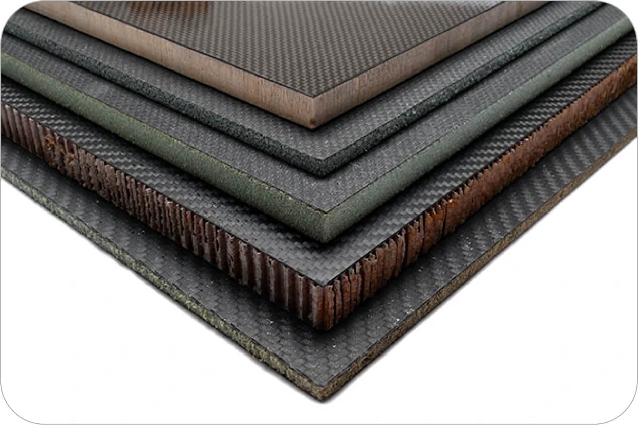
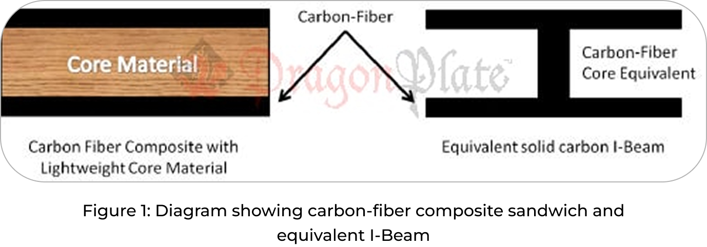
A composite sandwich structure strategically combines the high strength and stiffness of carbon fiber (or other fiber-reinforced plastics like glass or aramid) with a low-density core material, such as foam, honeycomb, or balsa wood. By separating two stiff facesheets with a lightweight core, the resulting structure achieves a much higher bending stiffness-to-weight ratio than either material could provide on its own.
This approach is ideal for weight-sensitive applications, such as aerospace, robotics, medical devices, and performance automotive structures. A sandwich panel delivers the performance of a much thicker solid laminate without the associated mass.
Mechanically, a sandwich panel behaves similarly to a homogeneous I-beam in bending, where the outer fibers carry the bending stress, and the inner core maintains separation and resists shear. This concept is illustrated in Figure 1, where a carbon-fiber sandwich is shown as a lightweight analog to a solid I-beam.
Composite Sandwich Structure
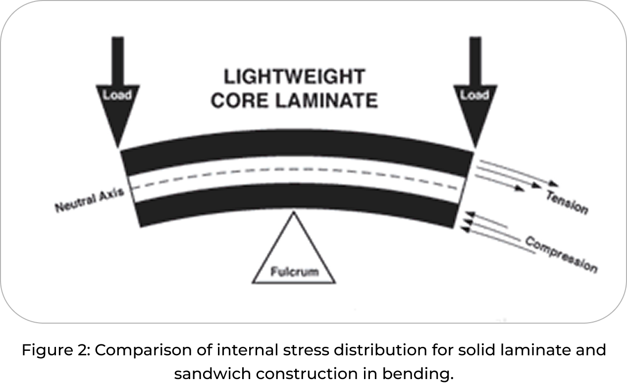
To understand how a sandwich panel resists bending, consider the internal stress distribution shown in Figures 2 and 3. In both cases, the neutral axis lies at the mid-plane of the beam (assuming symmetric construction).
This is the region where internal axial stress is zero. As one moves farther from the neutral axis — either up or down — internal stresses increase, shifting from compression on one side to tension on the other.
Stress Distribution in Sandwich Structures
Figure 2 shows the stress distribution in a lightweight core laminate (i.e., a sandwich structure). The outer carbon fiber facesheets carry most of the tension and compression loads. The longer force vectors near the top and bottom surfaces illustrate this increasing stress with distance from the neutral axis. Meanwhile, the low-density core contributes little to axial load bearing but maintains geometric separation and resists shear.
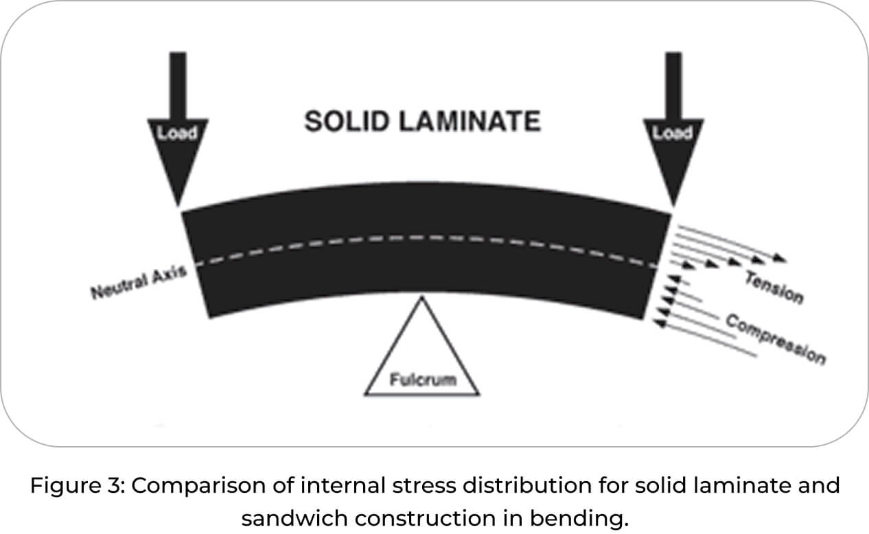
Maximum Bending
Figure 3 shows the same bending scenario applied to a solid laminate. While the internal stress distribution is similar in shape, the material between the top and bottom surfaces is all structural. This adds weight without proportionally increasing bending stiffness.
DragonPlate Sandwich Sheets
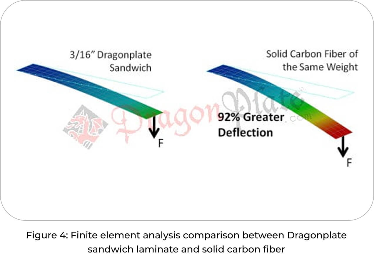
As an example, FEA analyses comparing a Dragonplate birch plywood sandwich laminate with a solid carbon fiber are shown in Figure 4. These calculations show the deflections of a cantilever beam with a load placed at the end. In the figure, 3/16” Dragonplate sandwich sheet is shown next to a solid carbon fiber layup of equal weight. Due to the reduced thickness of the solid carbon beam, it deflects significantly more than the equivalent beam made using a plywood core.
Large Weight Savings
As the thickness increases, this disparity becomes even greater due to the large weight savings from the core. For example, if instead the core material is foam or honeycomb, the disparity in deflection for equivalent weight panels can be several orders of magnitude.
In a similar light, one can replace a solid carbon structure with a lighter one of equivalent strength and stiffness. This latter case is common for currently operational structures that one needs to lighten, yet retain the original functionality.
NYSTAR Grant
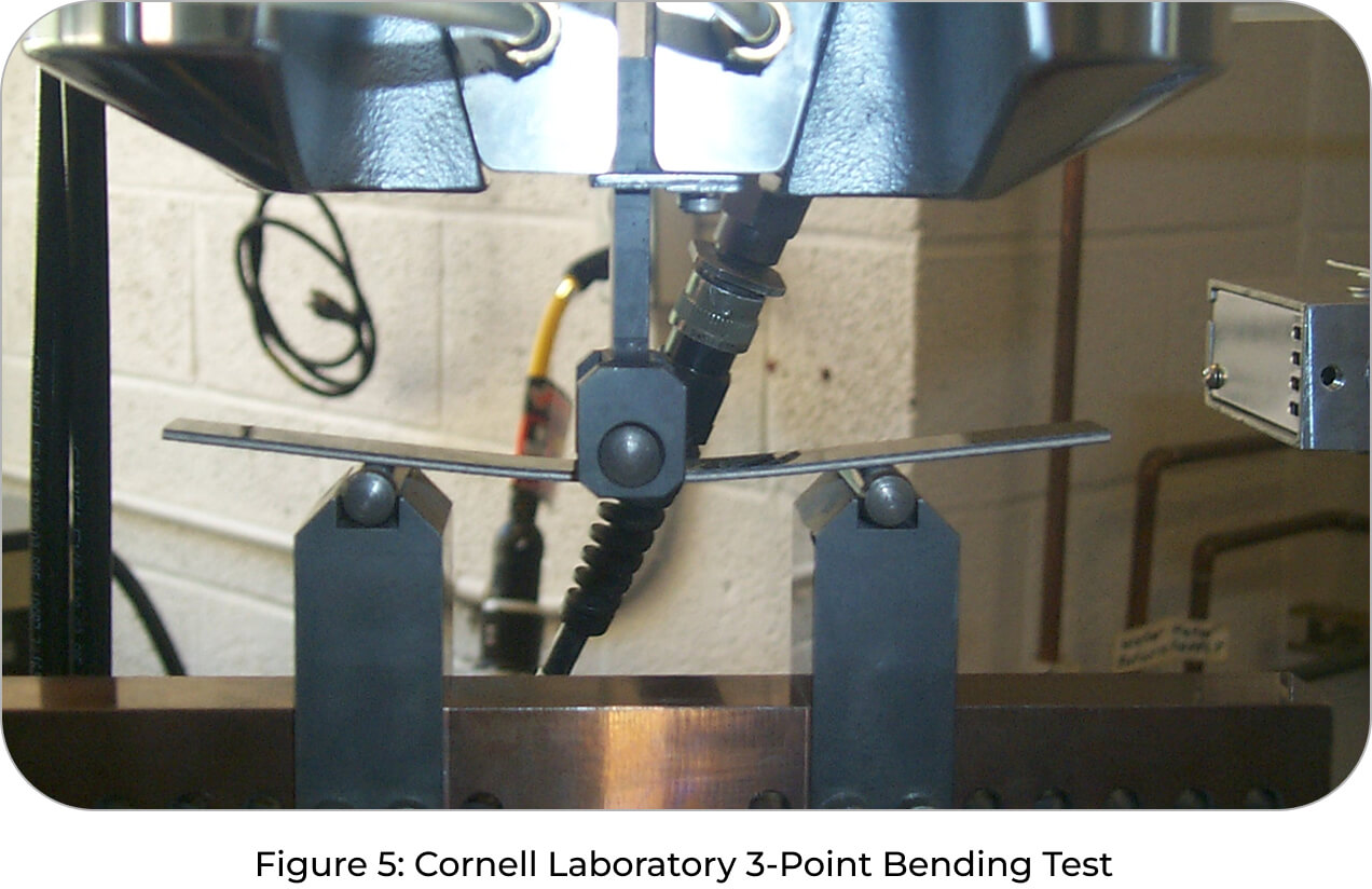
Through a grant from NYSTAR, Element 6 Composites has worked with Cornell University to test Dragonplate carbon-fiber composite materials.
Figure 5 shows a piece of Dragonplate undergoing a 3-point bending test. In addition to bending, the Cornell laboratory performed tensile, shear, and fracture testing.
Carbon Fiber Specialists